Let's Understand How a CPU Works
Designing a CPU from the ground up, with no knowledge needed
Chapter 11 - Building a Register
Topics Covered: Flip-Flop, Registers, Rising/Falling Clock Edges
In the previous chapter, you were introduced to the idea of non-determinism when we took the output of a circuit and fed it in as one of the inputs. This concept, which probably confused you at first at necessitated a reread of Chapter 10, allows us to store information in logic gates. We ended Chapter 10 by constructing a latch: a sequential circuit that allows us to store information. In this chapter, we have two main objectives: fix a shortcoming of the latch and use multiple latches to store more than 1 bit of data. In Chapter 7, you learned how to build a 1-bit adder and subsequently scaled that up to an 8-bit adder in Chapter 8. Similarly, in Chapter 10, you learned how to store one bit of data, and in this chapter we will scale it up to build a multi-bit data storage circuit known as a register.
An issue with Latches
Say we had a single full-adder being used to add two 1-bit numbers, and also suppose that we would like to store the output of this adder in a latch. This may seem easy enough: just take the output of the full-adder and feed it into the latch. Unfortunately, that is the easy part; the difficulty comes in determining how to actually save the value into the latch. Assuming we are using a positive-latch, we know that the input is only being captured when \(D = 1\). So, we would need to set \(D=1\), then set the two inputs to the full adder, and then set \(D=0\) to lock the value into the latch. It is important that we do not change the values of the inputs to the adder before we let \(D\) go from \(1\) to \(0\) or else we will end up latching in the incorrect output to the adder. For issues that will not become fully apparent until we have more than one component in our computer, it is problematic that our latch is updating its value whenever \(D = 1\). Instead, we would prefer a circuit that updates it’s value only at a specific time.
Whereas a positive latch updates its value whenever \(D=1\) and fully locks it in when \(D\) goes from \(1\) to \(0\), we would like a circuit that only updates it’s value at the exact moment \(D\) goes from \(1\) to \(0\). In other words, when \(D\) is either \(1\) or \(0\), the output in the circuit should never change. When it is time to update the value in the circuit, we need to have \(D\) go from \(1\) to \(0\). This means that our circuit can only update at an immediate, specific time. This introduces less issues since the value in the circuit only updates at a specific moment instead of updating whenver \(D=1\). It may not be entirely clear why the described circuit is better than a latch, because in this scenario, either circuit would suffice. In future chapters, the need will become apparent when we have multiple data-storage circuits and we only want to update one at a time. What you should understand, though, is the new circuit I am attempting to describe. A circuit that doesn’t update its value whenever \(D=1\), but instead only at the exact moment \(D\) goes from \(1\) to \(0\).
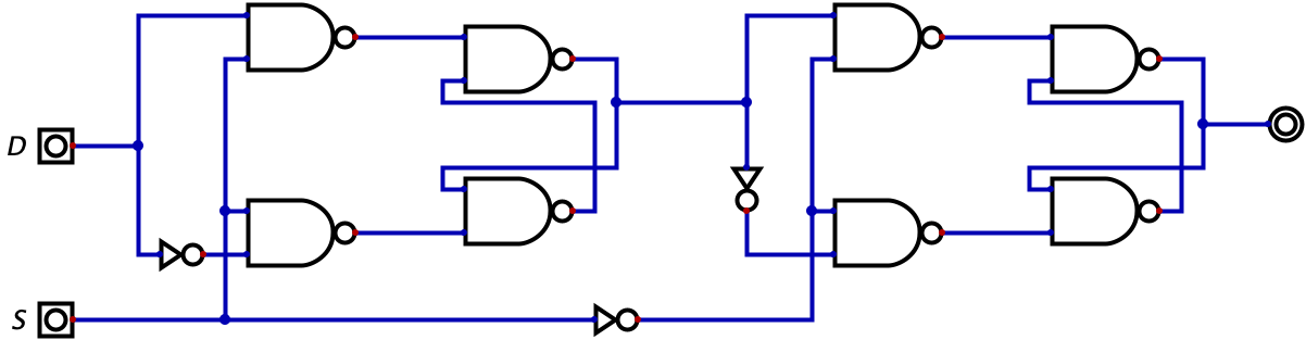
As you may have guessed, this circuit is popular enough to have a name: the flip-flop. And even more interestingly, it turns out we can built a flip-flop by using two latches. That’s right, the shortcoming we identified with the latch can be fixed by simply using two latches. This circuit, as was the case with the latch in Chapter 10, is hard to conceptualize. So, I will give you the circuit below, let you try to reason through it, and then I will offer an explanation to help your conceptualization.